
Introduction
Almost every motor drive inverter in the market rely on Pulse-Width Modulation (PWM) to synthesize the output current waveform. Because of that, the actual instantaneous voltage waveform at the inverter terminals will consist of very steep flanks at the beginning and end of each pulse. This is the origin for a multitude of negative effects on the connected equipment.
This post is part two of four:
- Reflections causing voltage doubling at the equipment terminals, causing increased stress on winding insulation
- Bearing currents inside electrical machines due to capacitive currents and non-uniform voltage and current distribution in windings
- Capacitive ground currents
- High frequency noise
Bearing currents
Background
For fast switching applications, such as PWM drives where the dV/dt is high, the common mode capacitive coupling generates charging currents which flow in the rotor shaft and exit through the end-bearings of the machine. This can damage the machine bearings and substantially decrease their life expectancy.
Effects
There are two types of bearing currents, separated by their paths inside the machine and their source of origin;
Non-circulating type bearing current
![Figure 1: Bearing currents with ground return in an electrical machine [2].\( C_g \) corresponds to the capacitance across the bearing while \( C_{ws} \) and \( C_{wr} \) corresponds to the per unit length parasitic capacitance from the winding to t…](https://images.squarespace-cdn.com/content/v1/584729023e00bebf8abd6ba0/1498471238118-PQ64YCC1QB458BOR37V0/image-asset.png)
Figure 1: Bearing currents with ground return in an electrical machine [2].
Cg corresponds to the capacitance across the bearing while Cws and Cwr corresponds to the per unit length parasitic capacitance from the winding to the stator and rotor respectively. Zinv is the (mainly) capacitive coupling from the inverter to ground.
This type is illustrated in figure 1. A simplified inverter with only one phase (phase a) with an impedance Zinv between the DC-link and ground serves as the source of the bearing current Ibrg. The current flows from the inverter into the motor main windings where the capacitive coupling between the stator winding and rotor Cwr starts to conduct charging currents in the rotor shaft.
The air gap capacitance Cg corresponds to the capacitance across the end-bearings which will serve as the bearing current's exit from the rotor back to the stator frame. Because the stator frame is grounded, the bearing current will return to the inverter through earth and the (mostly capacitive) impedance Zinv [1].
As the bearing current circulates back to the inverter rather than inside the machine, this type is referred to as non-circulating type.
Circulating type bearing currents
It has been found in [2] that non-circulating currents does not account for all the bearing currents discovered in practical experiments. From this arises a new type of bearing current which is not generated by the parasitic capacitive coupling between the rotor and stator alone. Instead, it arises from electromagnetic induction caused by a stray magnetic flux field raised by uneven current distribution in the winding coils.

Figure 2a: Stray capacitances between winding and stator iron which cause capacitive ground currents and subsequent non-uniform current density.
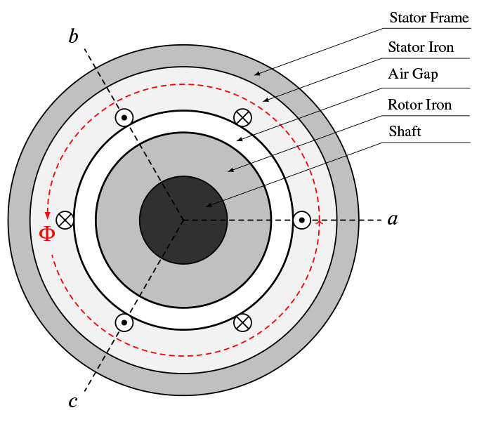
Figure 2c: Cross-sectional view of the machine where the net flux path of the enclosing magnetic field is show in red.

Figure 2b: Current density as function of winding length from terminal.

Figure 2d: Side view of the machine where the circulating bearing current is shown in red.
Figure 2: Stray capacitances in the stator winding causes leakage currents (a) which in turn causes uneven current distribution in the winding turns (b). This creates a flux field (c) which generates circulating bearing currents (d).
This uneven current distribution is caused by the high dV/dt which generates capacitive currents to the stator iron. As these currents are higher in the terminal-ends of the winding than in the far end, it creates a current unbalance in each of the two coil sides as shown in figure 2a and 2b. The current unbalance creates a net current flowing in the rotor shaft direction. According to Gauss' law, this current must create a net flux field. When this is surrounding the rotor and stator frame as shown in figure 2c a flux linkage is achieved and voltage will be induced in the rotor shaft (figure 2d).
From the rotor shaft, the current will exit through one of the end bearings and enter the stator frame and circle back to the rotor through the opposite end bearing, hence the name circulating bearing current as it is circulating inside the machine and not back to the inverter.
Origin
Common for both types of bearing currents is that they are formed on the basis of the common mode voltage. This voltage source is based on the difference between the non-zero sum of the three instantaneous PWM voltages and the ground potential and is illustrated in figure 3. This voltage will be referred to as the zero sequence voltage, V0.
![Zero sequence voltage (\( V_0 = 𝑉_{ph_gnd}\) ) in PWM inverter drives [3]](https://images.squarespace-cdn.com/content/v1/584729023e00bebf8abd6ba0/1498474350416-MDU7RUOX4J9WLAAEYF0X/image-asset.png)
Zero sequence voltage (V0=𝑉phgnd ) in PWM inverter drives [3]
The zero sequence voltage is proportional to the DC-link voltage, which for marine low voltage power systems often is approximately 975 V. The frequency is equal to the inverter's switching frequency [3].
The zero sequence voltage will act as a voltage source between ground potential and the aforementioned aggregate terminal voltage on the inverter side. This voltage potential in combination with high frequency and high dV/dt will generate currents between the ground potential and and parasitic elements in the circuit. These currents are often referred to as common mode currents or zero sequence currents.
Although the frequency of the zero sequence voltage was said to be equal to the inverter's switching frequency, the harmonic frequencies of the zero sequence currents exists over three different ranges [3, 4]:
- The fundamental frequency of the main inverter load. Typically between 6 and 60 Hz for marine applications. Zero sequence currents at this frequency range is not a result of inverter characteristics, but rather cable asymmetry, typically with regards to cables with single earth wire which has induced voltage from the main three phase conductors.
- The switching frequency from the inverter. This range is normally around a few kHz in marine applications and is also the fundamental frequency for the zero sequence voltage. Because of the relatively low frequency, the majority of the zero sequence currents returns to the inverter through ground rather than through bearings as the bearing impedance is too high at this frequency range.
- Resonant frequencies triggered by inverter switching. This range is dependent on the switching times and dV/dt from the inverter switching devices and can vary from 50 kHz to 5 MHz when using of IGBT switches. This frequency component is considered to be the largest part of the zero sequence current and the main cause of all bearing currents in PWM drives [3].
Consequences
Because the dV/dt occurs at a high frequency, bearing currents are often pulsating rather than flowing steadily [3]. This causes additional stress on the bearings and failure modes such as pitting, fluting and false brinelling can occur. All which will reduce the life expectancy of the bearings significantly [5].
In addition to damage the motor bearings, the bearing currents may conduct through the shaft and exit inside connected mechanical loads or gears. These components can also take serious damage from EDM.
Remedies
- Establish equalizing paths for HF zero sequence currents:
- Provide a low impedance path for HF zero sequence currents back to the inverter frame. Ordinary grounding will not be suitable due to the nature of HF currents and the skin effect. Normally this path is achieved by using steel- or aluminum cable braiding with special type HF blocks to provide a 360 degree clamping around the cable and achieve a large contact surface in both ends.
- Low impedance potential equalization between all parts and components on the motor side of the installation. This includes bonding between motor frame and motor terminal box, motor frame and ground, motor frame and connected mechanical load (or gear) and between inverter frame and ground.
- Utilize motor cables with circular conductor cores with either no separate earthing conductor or with three symmetrical placed earthing cores to prevent induction of voltage in to the earth potential.
- Use insulated motor bearings in one or both ends of the machine.
- Reduce the dV/dt on the output of the inverter terminal by applying chokes or filters:
- Zero sequence chokes, e.g. ferrite rings (also called iron cores) around all three output phases from the inverter to dissipate high frequency noise.
- Apply a three phase sinusoidal filter.
With the exception of output filters, all of the above practices are common on marine motor drive applications, but the vendor has to ensure that the contractor installs the HF equalization bonding correctly to ensure an effective measure against bearing currents and the other negative side effects of zero sequence currents.
Sources:
E. Persson. “Transient effects in application of PWM inverters to induction motors”. In: Pulp and Paper Industry Technical Conference, 1991., Conference Record of 1991 Annual. June 1991, pp. 228–233. DOI: 10.1109/PAPCON.1991.239644.
Shaotang Chen, T.A. Lipo, and D.W. Novotny. “Circulating type motor bearing current in inverter drives”. In: , Conference Record of the 1996 IEEE Industry Applications Confer- ence, 1996. Thirty-First IAS Annual Meeting, IAS ’96. Vol. 1. Oct. 1996, 162–167 vol.1. DOI: 10.1109/IAS.1996.557010.
P.J. Link. “Minimizing electric bearing currents in adjustable speed drive systems”. In: Pulp and Paper Industry Technical Conference, 1998. Conference Record of 1998 Annual. June 1998, pp. 181–195. DOI: 10.1109/PAPCON.1998.685519.
J.M. Bentley and P.J. Link. “Evaluation of motor power cables for PWM AC drives”. In: Pulp and Paper Industry Technical Conference, 1996., Conference Record of 1996 Annual. June 1996, pp. 55–69. DOI: 10.1109/PAPCON.1996.535983.
J.L.H. Silva and A.J.M. Cardoso. “Bearing failures diagnosis in three-phase induction mo- tors by extended Park’s vector approach”. In: 31st Annual Conference of IEEE Industrial Electronics Society, 2005. IECON 2005. Nov. 2005, pp. 2591–2596. DOI: 10.1109/IECON. 2005.1569315.