In this post I will try to gain som insight into the design of a small commercial motor drive. The unit in question is a small 1/2Hp (372 W) drive from TECO. The power supply to the control logic is broken, and because of it's small size(i.e. cheap) I did not bother to try and fix it.
The circuit board is clearly damaged by the heat from some kind of component failure.
The main emphasis will be on the power circuit, the cleverness of the controller will be hidden in the software and thus it will be little knowledge to gain from trying to redraw the entire circuit diagram.
Power circuit
By inspecting the circuit boards I have attempted to redraw the high power portions of the circuit.
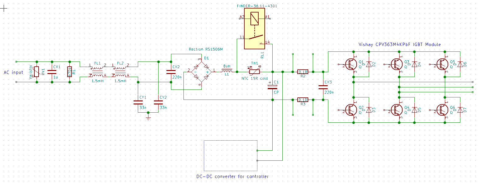
Redrawn diagram of the main power circuit.
The input voltage is \(230 \;V \;AC\) at \(50 \; Hz\). The input is protected by a metal oxide varistor. Following the MOV is a filter consisting of several capacitors and inductors.
A RS1506M full bridge rectifier module is used to convert the incoming AC to DC.
Inverter power circuit board. The large capacitor to the right is the main reservoir capacitor, while the inrush limiting NTC is the black body just above the capacitor. The rectifier and inverter modules are visible at the top left and right respectively.
On the DC side of the rectifier a NTC resistor is used to limit the inrush current to the main reservoir capacitor. A relay is used to bypass the resistor, presumably when the capacitor is fully charged.
Two \(0.1 \Omega\) resistors are connected in series with the inverter module, one in the positive and one in the negative side of the DC-bus. These resistors are likely used to sense the current.
The inverter consists of a CPV363M4KPBF IGBT module from International Rectifier (now Infineon). The inverter is controlled by a IR2133J gate driver, not shown in the schematic.


Input filter
Please refer to the schematic of the input filter for the following discussion. The input filter consists of two X-rated and two Y-rated capacitors, as well as two common mode chokes connected in series.
The X, and Y rating of capacitors is used to guarantee the safe performance in mains applications.

Input filter to the rectifier. The two yellow bodies contains the common mode input chokes. The blue component to the left is a metal oxide varistor to protect the input from overvoltage. The other blue components are various sizes of capacitors.
A X-rated capacitor is intended to be connected line to line, to filter common mode noise. When a capacitor fails catastrophically it will either become a open circuit or a short circuit. Thus if this happens to a X rated capacitor used correctly, one of two things will happen. It will either simply be removed from the circuit, degrading the performance, or it will short circuit blowing the the fuse or circuit breaker in the input. In either case the failure will impose no risk to the user as long as the external fuses are properly dimensioned.
The Y-rated capacitors are intended to be connected from line to ground, filtering asymmetrical noise. I.e. the capacitor is connected between the power lines, and the metallic chassis of the device in question. Thus in this case if the chassis is not properly grounded(as it should be) there will be a risk of electric shock if the capacitor short circuits.
The main difference between these capacitors and regular capacitors are strict requirement to evaluation of the performance. E.g. voltage impulse tests. The classification of safety capacitors of this type is provided in IEC 60384-14, which unfortunately isn't publicly available(i.e. you have to pay for access).
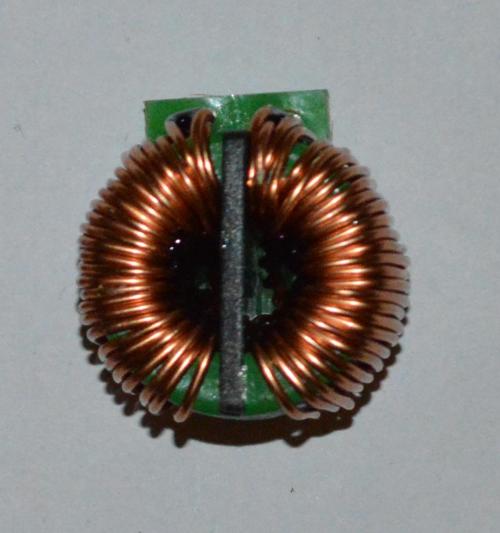
Filter choke consisting of two separate inductors wound on the same magnetic core. The black plastic piece in the middle separates the two inductors. Two wires are used in parallel, in order to increase the current carrying capability.
Common mode choke
The common mode choke consists of two wires wound on the same magnetic core. When measuring the inductance using a regular L-meter, the reading says \(1.5\;mH\), this may not be the reality however. The idea is that the magnetic fields induced by the differential mode currents in the windings will cancel each other out, thus the inductor will present little reactance to such currents.
The inductance to common mode currents however will be high.
As a side benefit the core is less likely to saturate, as it is normally operating with a low magnetic field. Thus the constraints on the current carrying capability is not determined by the saturation limit, but by heating of the windings. I.e. a smaller magnetic core may be used.
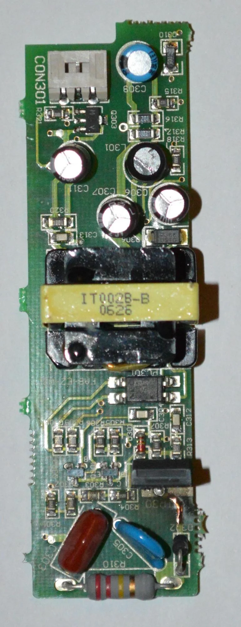
DC-DC converter
In order for the control circuitry to have power, a DC-DC converter is used. This is the component that appears to have failed for some reason.
On the primary side of the transformer there is a Toshiba K2700 N-channel MOSFET, that is used for chopping of the DC-link voltage.
There are no integrated controllers for the converter, only some discrete components. Among those are two small transistors, possibly forming a astable multivibrator to generate the control signals for the switching MOSFET.
There is also a opto-coupler feeding a signal from the secondary side of the transformer back to the oscillator. This is likely the feedback signal used to maintain stable voltage on the secondary.
The secondary side consists of some rectifier diodes, a filtering inductor, and some filtering capacitors. There is also a connector for the cooling fan.
Control circuit
The controller consists mainly of a integrated circuit labeled: "TECO E2 V2.3". It is likely that this is some kind of microcontroller, or ASIC. It has some analog, and digital I/O, some push buttons, a 7-segment display, and a interface to the gate driver.
Controller board. The TQFP packaged chip is the controller. The screw terminals at the top are available for connection of external I/O. The blue component to the top right is a relay used for digital output.
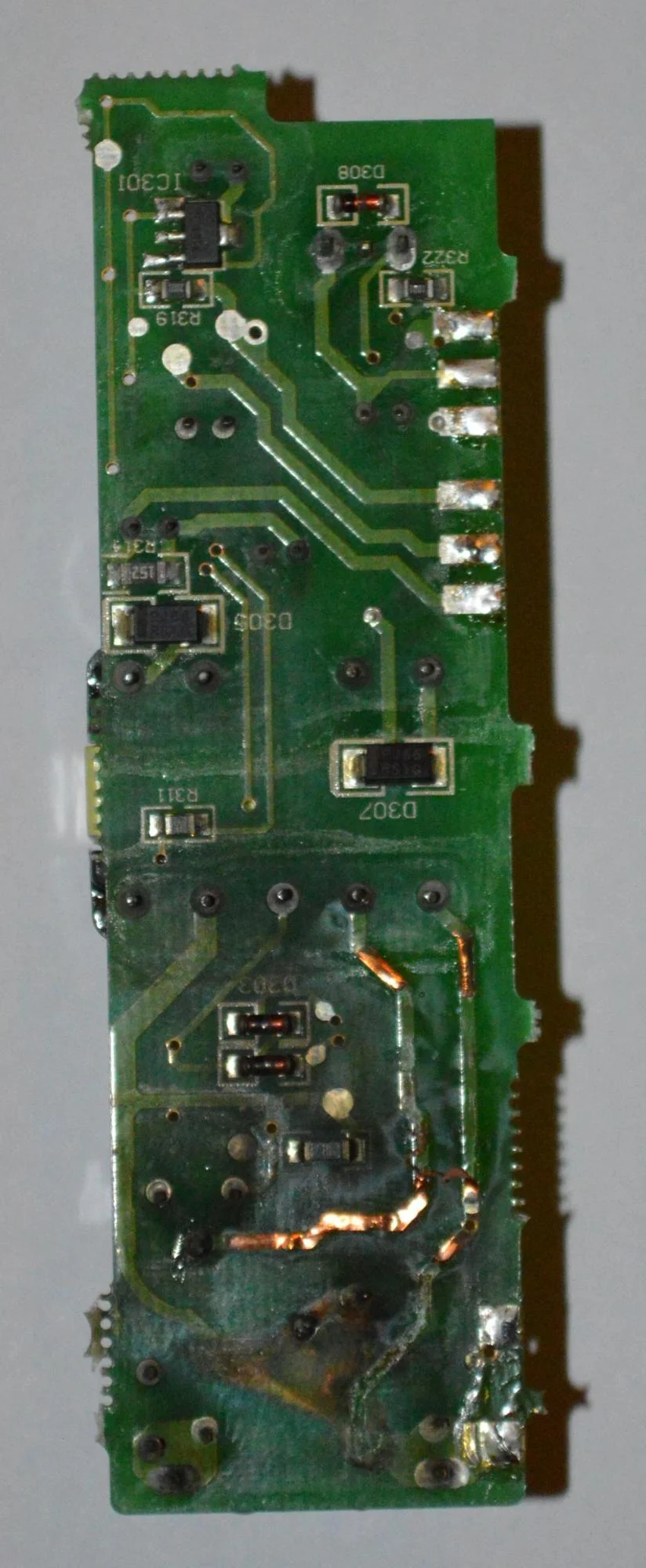
Bottom view of the controller circuit board. The SOIC(Gull-Wing) packaged chips are opto-couplers most likely used for the digital I/O.