Introduction
During the last few years a new generation of high power switches has emerged in the semiconductor industry and start to become commercially available. The use of Silicone Carbide (SiC) based devices promises a significant reduction in switching losses and permits far higher switching frequencies than what is possible today using pure Silicone (Si) devices.
This article will provide a brief intro to the differences between Si and SiC devices used in power electronics.
SILICON CARBIDE ENTERING THE MARKET
SiC as a semiconductor material has been under development for over two decades. Mitsubishi Electric started researching elemental SiC technologies in the early 1990s [26]. Their first com- mercially available product using SiC devices was launched mid 2011 in an inverter used in the home air conditioner "Kirigamine" [26]. Later, the world’s first all-SiC powered traction system was installed in the Shinkansen Bullet Trains in Japan, as late as June 25 2015 [25].
Where traditional Silicon (Si) based switches for power applications have been based on bipolar devices such as Insulated Gate Bipolar Transistor (IGBT), the first available SiC devices have been unipolar devices such as Junction gate Field-Effect Transistor (JFET) and Metal–Oxide–Semiconductor Field-Effect Transistor (MOSFET) (the latter with and without additional body diode). However, SiC based IGBT and thyristors are currently under development [5] [27] [15].
Currently, the only available IGBT-based SiC-devices are so-called hybrid devices with traditional Si transistor and SiC Schottky Barrier Diode (SBD).
SiC benefits
There are three main physical characteristics of SiC semiconductors which makes it superior to ordinary Si devices [23]:
- Lower leakage currents. Electron-hole pairs generates much slower in SiC than in Si. This will reduce the leakage current losses when the switch is off compared to Si at a given temperature.
- Increased critical breakdown strength. This implies that the device can withstand a higher voltage in the same package, or the package insulation can be reduced at the same voltage rating. Devices like MOSFET, JFET and the SBD can thereby be created at blocking voltages approximately an order of magnitude higher than what is possible with Si [7].
- A higher thermal conductivity allows for more efficient transportation of heat from the device. Additionally, the on-state resistance through the switch is lower, causing decreased conducting losses.
Si diode turn-on
SiC SBD turn-on
Figure 1: Comparison of turn-on values for voltage, current and power between SiC and Si-diodes.
The reverse current overshoot which causes energy loss is indicated by red cross-hatches. The devices are 1200 V Cree/Wolfspeed Si Ultrafast Diode and SiC SBD at 125 °C [14]
Si diode turn-off
SiC diode turn-off
Figure 2: Comparison of turn-off values for voltage, current and power between SiC and Si-diodes.
The recombination charging which causes energy loss is indicated by red cross-hatches. The devices are 1200 V Cree/Wolfspeed Si Ultrafast Diode and SiC SBD at 125 °C [14]
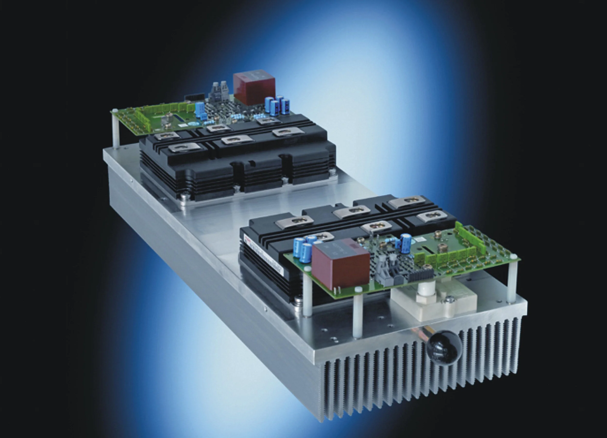
Figure 3: An exploded IGBT power module showing the bottom circuitry with transistors (squares with black edges) and anti-parallel diodes (gray squares).
In conventional bipolar Si switches, e.g. IGBT, the switching frequency is limited by the time required for the plasma in the drift region to establish and be removed. For unipolar SiC devices this limit does not apply, allowing significantly higher switching frequencies [3].
To achieve a fast switch transition, the peak gate current value is critical in combination with the design and operation of the gate driver stage [23].
Improvements to gate driving techniques can decrease switching losses caused by parasitic inductance by countering these effects and thus allow the removal of the damping resistor in the gate path used in MOSFET applications [3]. This aspect will not be covered in this post.
SiC diodes, like the SBD, are also contributing to decreased losses in power converters; they exhibit significantly decreased reverse recovery voltage and reduced reverse current overshoot. These properties results in a major decrease in commutating losses. This is shown in figure 1 and 2.
An Intelligent Power Module (IPM) is a unit consisting of several transistors and diodes supplied as one unit, thus making design of the power conversion equipment easier for manufacturers. An IPM produced by Semikron is shown in figure 3 for illustration purposes. Because IPMs are the device type of choice for equipment manufacturers in the marine power conversion industry, this report will as much as possible focus on that type of device.
Parameter comparison of Sic devices
As high-power SiC based modules has though just recently gotten commercially available, the ma- jority of research has been focused on optimizing gate driving techniques and to adapt circuitry to counter the effects of SiC parasitic elements. The consequences and possible remedies for the load side connected equipment are not investigated to the same degree.
To examine the possible 𝑑𝑉 ∕𝑑𝑡 in available and upcoming products, data sheets from leading providers will be studied. Rise and fall times during transistor switching as well as energy loss will be compared. Because manufacturers does not specify their devices’ properties under the exact same conditions, some of the results will not be directly comparable between devices from different manufacturers.
In the following comparison, three main configurations of Si/SiC-devices are treated;
- Si, which is the traditional device with Si based IGBT transistor and freewheeling diode,
- Si-SiC, which is based upon Si IGBT and a SiC freewheeling diode. This configuration is also referred to as Hybrid-SiC devices.
- SiC, which is based on either MOSFET or JFET SiC transistor with a SiC SBD.
As of now, at least five major manufacturers of power electronic components are either mass producing or offering test samples of SiC based power modules for power electronics producers. Their approach and selection of Si/SiC configuration and type of transistor is varying and is therefore included in the following list.
- Mitsubishi Electric: Si-SiC with SBD and MOSFET-based SiC IPMs. Mass production started of select devices, but no datasheets are available on their website as of December 2015.
- Semikron: Si-SiC with SBD and MOSFET-based SiC. Samples available for equipment man- ufacturers. Datasheets are available, but their contents are not guaranteed for final released devices.
- Infineon: Offers Si-SiC with Si IGBT and SiC SBD. Commercially available, but production scale unknown.
- Rohm: Offers both Si-SiC with SBD and double-implanted MOSFET-based SiC. Commercially available.
- Wolfspeed (prev. known as Cree): Offers MOSFET-based SiC devices. Commercially available, production scale unknown.
The mentioned manufacturers are constantly improving their voltage and amperage rating of their SiC devices and complementing their assortment with new devices. Because of this, some of the devices mentioned in this report might not be commercially available at the time of printing, and the datasheet values might change up till commercial release.
Comparing Si and SiC power modules
To illustrate the differences between Si based and SiC based power modules, a comparison has been made between similar rated devices from two leading power transistor manufacturers; Infineon and Semikron. The three other aforementioned manufacturers were also considered, but none of them had comparable power modules at the time.
From numerous other papers, it has been measured considerable reduction in energy loss on transistor and diode level. A comparison between actual, commercially available IPMs can pro- vide a more realistic picture on how much energy can be saved in an actual industrial application. Note that this comparison is using the manufacturer’s data as basis, and that the numbers are not guaranteed.
Based on the current available datasheets from Infineon and Semikron, the following five 1200 V halfbridge power modules are compared:
- Semikron
- SKM200GB12T4SiC Si IGBT with SiC SBD (Si-SiC)
- SKM500MB120SC SiC MOSFET with SiC SBD (SiC)
- SKM400GB126D Si IGBT with Si diode (Si)
- Infineon
- FF600R12ID4F Si IGBT with SiC Diode (Si-SiC)
- FF600R12KE3 Si IGBT with Si Diode (Si)
In addition to the above mentioned manufacturers, Rohm, Mitsubishi Electric and Wolfspeed were queried about datasheets for power modules. Rohm and Wolfspeed did not offer IPMs for IGBT power modules (only SiC) while Mitsubishi Electric did not offer datasheets for SiC power modules.
Because each manufacturer are specifying their devices’ parameters in slightly different conditions, the comparison are made between devices from the same manufacturer.
From table 1 it can be seen that the most important reduction in energy loss is found in the diode recovery energy (𝐸𝑟𝑒𝑐) where this diode is made of SiC rather than of Si.
For MOSFET transistors, the internal body diode is sometimes sufficient such that there is no additional diode loss. Another interesting aspect is that the Si-SiC module has a lower 𝐸𝑜𝑛 than the MOSFET based SiC module. However, the difference between Si and Si-SiC’s 𝐸𝑜𝑓𝑓 compared to that of SiC is considerable.
These loss reductions makes it possible to increase switching frequency while maintaining the same losses as an Si-based power module. A different opportunity is to decrease component size and thus increase power per volume. This can lead to more compact equipment which is a very welcome property in the marine business as space is often limited.
| Item | Si | Si-Sic | SiC | Si | Si-Sic | Unit |
|---|---|---|---|---|---|---|
| Semikron | Infineon | |||||
| Collector-emitter voltage | 1200 | 1200 | 1200 | 1200 | 1200 | V |
| Nominal Current | 300 | 200 | 500 | 600 | 600 | A |
| Turn-on delay time | 330 | 185 | 270 | 660 | 200 | ns |
| Turn off delay time | 650 | 425 | 400 | 960 | 550 | ns |
| Rise time | 50 | 40 | 70 | 70 | 70 | ns |
| Fall time | 110 | 82 | 65 | 80 | 80 | ns |
| Turn on energy loss | 29 | 7 | 10.3 | 120 | 20 | mJ |
| Turn off energy loss | 48 | 20 | 4.7 | 95 | 40 | mJ |
| Diode Recovery energy loss | 27 | 0.1 | n/a | 17 | 10 | mJ |
| Total energy loss | 104 | 27.1 | 15 | 232 | 70 | mJ |
| Thermal resistance j/c | 0.08 | 0.14 | 0.07 | 0.0044 | 0.034 | K/W |
References
(in case you are wondering about the weird numbering; this post is an excerpt of a much longer report about filter design for SiC applicatons, written by Yngve Solbakken during the fall of 2015)
[3] P. Anthony, N. McNeill, and D. Holliday. “High-Speed Resonant Gate Driver With Con- trolled Peak Gate Voltage for Silicon Carbide MOSFETs”. In: IEEE Transactions on In- dustry Applications 50.1 (Jan. 2014), pp. 573–583. ISSN: 0093-9994. DOI: 10.1109/TIA. 2013.2266311.
[5] M. Bhatnagar and B.J. Baliga. “Comparison of 6H-SiC, 3C-SiC, and Si for power devices”. In: IEEE Transactions on Electron Devices 40.3 (Mar. 1993), pp. 645–655. ISSN: 0018-9383. DOI: 10.1109/16.199372.
[7] A. Elasser and T.P. Chow. “Silicon carbide benefits and advantages for power electronics circuits and systems”. In: Proceedings of the IEEE 90.6 (June 2002), pp. 969–986. ISSN: 0018-9219. DOI: 10.1109/JPROC.2002.1021562.
[14] Jim Richmond. Application Note: Hard-Switched Silicon IGBTs. May 2015. URL: http: //prf.cree.com/~/media/Files/Cree/Power/Application%20Notes/CPWRAN03B. pdf (visited on 09/27/2015).
[15] E. Johnson et al. “An analysis of paralleled SiC bipolar devices”. In: IEEE Power Electronics Specialists Conference, 2008. PESC 2008. June 2008, pp. 4762–4765. DOI: 10.1109/PESC. 2008.4592723.
[23] J. McBryde et al. “Performance comparison of 1200V Silicon and SiC devices for UPS application”. In: IECON 2010 - 36th Annual Conference on IEEE Industrial Electronics Society. Nov. 2010, pp. 2657–2662. DOI: 10.1109/IECON.2010.5675125.
[25] Mitsubishi Electric. Mitsubishi Electric Installs Railcar Traction System with All-SiC Power Modules on Shinkansen Bullet Trains. June 2015. URL: http://www.mitsubishielectric. com/news/2015/pdf/0625.pdf (visited on 09/09/2015).
[26] Mitsubishi Electric. SiC Power Modules. May 2015. URL: http://www.mitsubishielectric. com/semiconductors/catalog/pdf/sicpowermodule_e_201505.pdf (visited on 09/09/2015).